A while ago there was an outbreak of posts on peoples blogs which had five things about the blogger that you didn’t know about them. I had been thinking about writing some posts about this for my blog, but have been unable to come up with five interesting things. I have decided to post anyway.
The first is that I was enrolled into a BTEC National Diploma in Electronic Engineering at Crawley College, but changed this two months before the course started to Information Technology. I use to love building electronic projects. This love was fueled by an ITV childrens program called “Video and Chips” – a general technology program which introduced different technologies to kids. I was hooked on this program. I would watch every episode, and then have a go a making whatever they had been making, whether that be an electronic project, hovercraft, hot air balloon or whatever. Every week a different technology would be explained and a new project to construct a new toy. A stamped self addressed envelope assured your fact sheet that detailed each project for this TV program – I still have mine.
The second thing that fueled my interest in electronics was the shop along the road from me. In Handcross, the small village where I used to live, there were the usual range of village shops. There was, however, a ham radio specialist shop – a bit unusual for a small village. I cant ever remember more than one other customer when I visited. This shop stocked electronic projects which could be built by anyone with a soldering iron which I had developed an addiction to – I bought all of the projects that they stocked. Funnily enough, one of the engineers who worked at this shop had a sideline business of building PCs, and I convinced my Dad to buy a PC from him so that I could learn about them. It was a 286 with one meg of ram, a forty meg hard disk and a VGA monitor. It cost 550 pounds. Within a week I had deleted all of the files in the root of the drive which stopped it from booting – it got sent back to have the operating system reinstalled, and I never heard the last of it.
Why did I change my course to Information Technology? I cant quite remember. I think it might have been the maths involved in electronics – maths wasnt my strongest subject. Funnily enough electronics was one of the subjects on the IT course, and I remember tutor’s report saying “this student is not upto the BTEC standard”. Well that greasy haird hippy can stick that report – I now have a batchelors degree 🙂
Incidently, the first video and chips project that I built was called a trembler alarm – an alarm that detects vibrations. Here are the instructions for making it.
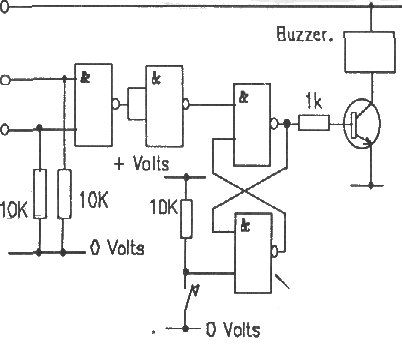
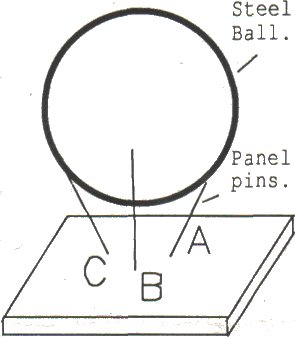
Description. The trembler alarm is an ultra sensitive alarm system, It can be made so sensitive that just tapping the table it is on will set it off. The Video and Chips trembler is built using one chip, a transistor, a buzzer, a few resistors, some thin electrical wire and a 6 to 12 mm steel ball. The electronics are very simple to construct although you will need to use a soldering iron so find an adult to help you get started with this project. The trembler is a steel ball sitting on three pins . The ball makes electrical contact with the pins and provided the ball is still the contact remains. If the ball moves, even for one 40 millionth of a second, the circuit is broken and the alarm is set off. Only pressing the switch will turn it off and reset the alarm.
 Construction. The trembler is built on small piece of wood, 25mm square. Three panel pins are knocked into the wood with about 15mm left sticking out and the ball is allowed to rest on these. They must be far enough apart to let the ball sit on them without rolling off but not so far apart that the ball falls between them. The best results come from splaying the pins a little once they have been knocked in.
The alarm circuit is built on a piece of strip board. Strip board has copper tracks on one side to conduct electricity while the other side is plain. The circuit is built up using the tracks on the underside and wires on the upper side. To start constructing you will need a piece of Strip Board about 50mm by 50mm. Use the board with the copper strips downwards and running from left to right across the board. Using the diagram below, place the components as shown into the holes. The dotted lines on the diagram are the tracks the components are shown and you should make sure that all the components are on the right tracks. The tracks underneath the Chip socket have to be cut. This can be done using a 4mm drill bit in a small hand brace. Take care not to drill through the board.
Soldering is an art but a very simple one. 1. Heat up the joint between the component lead and the copper strip with the tip of the iron. 2. Put some solder onto the joint keeping the iron on the joint also. 3. Keep the heat on the joint for a few seconds while the solder flows and then remove the iron. Make all the cross links using lengths of wire pulled down tight against the board. Connect the battery wires to the board RED to + Volts and BLACK to – Volts. Connect the buzzer between points buzzer 1 and 2. (Red to buzzer 1) Connect the switch across the points marked switch 1 and 2.
 Connect the three prongs of the tremble sensor to tremble A, B & C on the circuit board and place the ball on the prongs. Lastly solder the transistor in and plug the chip into its socket. The battery, circuit and trembler should all be attched to a single baseboard for ease of use.
Operation. The unit is tested by tapping the ball once the system is on. The push switch resets the alarm. If the circuit does not work the first thing to check is that the connections are all correct and that the chip is in the right way round. Next check that there are no solder bridges between tracks on the underside of the board. The sensitivity can be adjusted by moving the pins in and out. If they are close together the trembler will be very sensitive indeed. To use the device just leave it in your desk or in your bag. If any one or anything moves the bag or the desk the unit will sound the alarm.
Parts List.
– One 4011B Quad dual input NAND
– 0ne 14 Pin DIL socket for the Chip.
– One BC108 Transistor.
– Three 10K Resistors.
— One IK resistor.
— One Push to make switch. One PP3 Battery.
– One PP3 Eatery clip.
– One small piece of Stripboard (VEROboard)
– One 6-12 Volt buzzer.
— Some electrical wire.
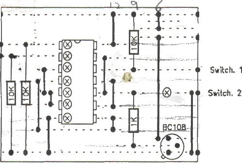 The strip board layout.The circuit is built on strip board with the components on top and A wire cross link. The circles with an X indicate a break in the track.
Interesting, electronics was a hobby that really pushed me into assembly (long story, many tangents, incredibly boring).
Tell me though, Joe: why is there a yeti in a blizzard with a flatulence problem struggling under the 10kΩ resistor immediately to the right of the IC in the final diagram?
Comment by Simon Butcher — October 31, 2007 @ 4:20 pm
Joe
The RS catalogue lists numerous possibilities for the 4011B Quad dual input NAND chip suggested for your trembler alarm of October 15, 2007.
Which one do you suggest?
Hamish
Comment by Hamish Moffatt — April 10, 2008 @ 10:28 am